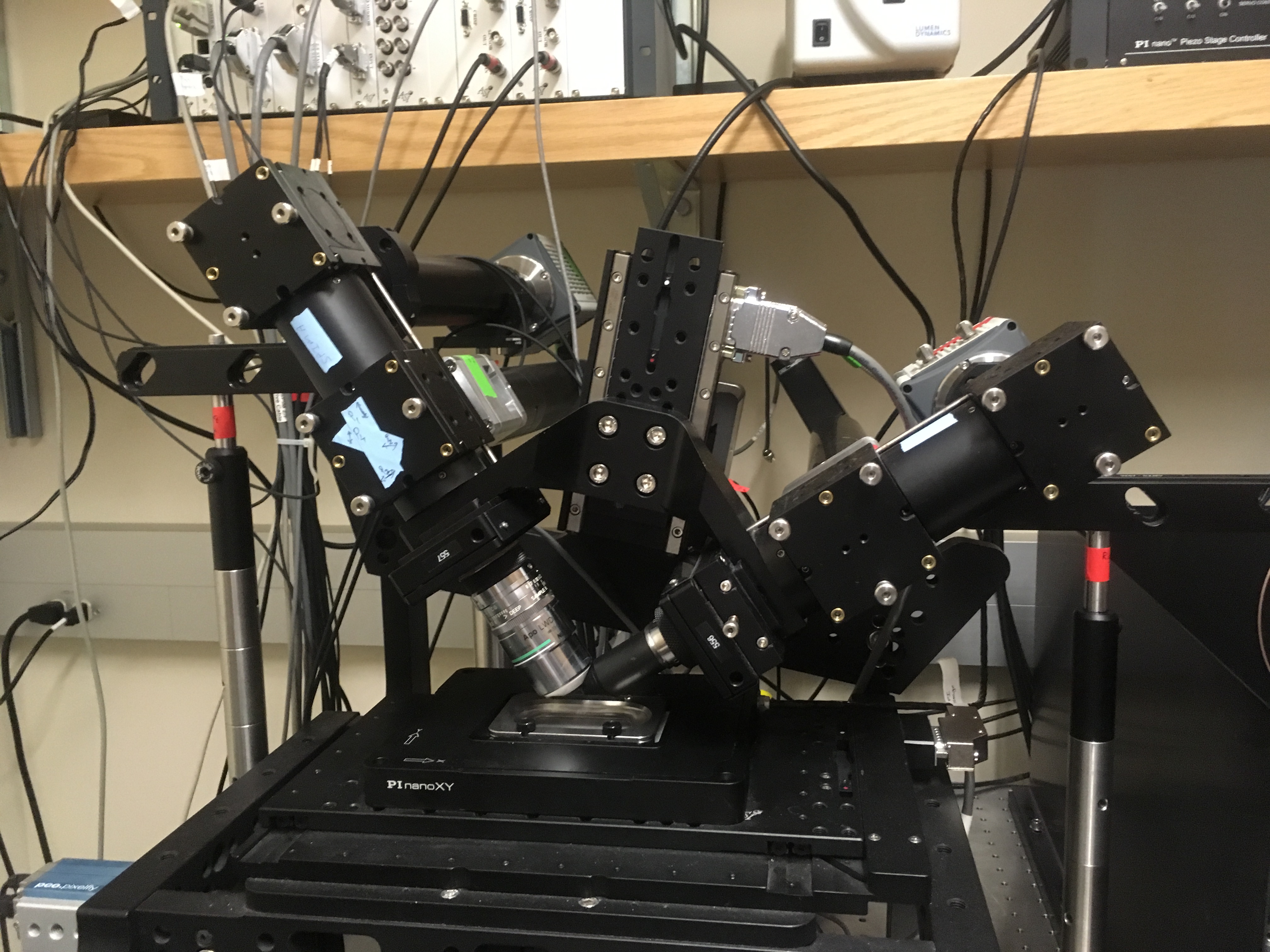
I am stunned alright, and there was only just the one diSPIM (Fig. 1). Missing from the picture and adding to the effect was the overhead box with lights flashing like a fireflies on arthropod ecstasy, and the meter square sandbox where lenses, mirrors, and beam-splitters played tag with a laser.
The highteckery is in the MBL ‘pop-up’ lab of Hari Shroff, one of the main inventors of diSPIM and a leading practitioner of the art. He had given me the special large coverslips for use in the microscope and I stained-up and mounted some BY2 cells thereon. We walked across the street to where his second diSPIM lives, the high resolution version, and the one that has polarizing gear attached. With us was Talon Chandler, a grad student working with Rudolf and Patrick LaRivierre on three-D polarized light algorithms. Driving the ‘scope was an energetic postdoc called Min. He showed us his schedule on the instrument – huge blocks of time booked, right up to the hour when they dismantle and move it back to NIH. I wondered when he ate or slept.
What is diSPIM? The acronym stands for dual view inverted selective plane illumination microscopy. Words are better than letters but hardly self explanatory. To begin, even tho the acronym has no F, diSPIM is a kind of fluorescence microscopy. In customary fluorescence rigs, the light that excites fluorescence in the sample comes either from above or below the sample, but in-line with the optical axis of the microscope. But take a look at Figure one: The two lenses shown are at 90? to each other. Hmm, maybe the ‘di’ should stand for ‘diagonal’?
This 90? business results from the ‘selective plane illumination’ (SPI) bit of the acronym. In this kind of microscopy, the light that shines on the sample is a sheet, not a cone. In a common or garden microscope, there are two major lenses, one on either side of the sample. The objective lens is between the sample and your eyes (or the camera), comes in different magnifications (10x, 20x, etc.) and is what you adjust when you bring the sample into focus. But there is a second lens, the condenser. This one is between the sample and the light source and it brings the light to a focus at the sample. The condenser also has to be focused tho not everyone knows how. The condenser and the objective are spherically symmetric so the light passing through is in the form of a cone.
In a ‘light sheet’ or ‘selective plane’ microscope, instead of a cone, light comes in a sheet. In the first devices of this kind, a cylindrical lens was used that made an actual sheet of light. But more recently, a regular (i.e., spherical lens) is scanned up and down, which makes a sheet of light over the time of a scan. Wow! Illuminating the sample with a sheet of light, sounds pyrotechnical, but why bother?
It turns out, for reasons that would take a bit of a course in optics to explain (hint – I don’t really understand) a light sheet arrangement needs less light to excite a given amount of fluorescence than does a light cone. This matters when you want to image a thing that is easily damaged by light (for example, a living thing). Fluorescent molecules in a living cell are often few in number and so a ton of photons are dumped on the sample to light it up, often bleaching the dye or killing the cell. Light sheet microscopes are popular because they spare the tender cell from laser-sunburn.
But as usual there is a catch. The light sheet has to come in from the side, not from the top or bottom. That is the 90? thing. In the first kinds of light sheet microscope, the sample had to be put in a thin, vertical capillary tube with the lenses horizontal. This was fine for eggs and other small things that could be stuffed into such a capillary but more or less useless for tissue of any kind. I did manage once squeezing an arabidopsis root into one of those capillaries by dint of messing around with syringes and lots of cursing. The newer kind of light sheet instrument (as in the one pictured) puts both lenses above the sample (at 45? and places the sample in a bath beneath them (see the silver small bathtub in the picture). Hence the designation ‘inverted’ and the ‘i’ in diSPIM. These lenses are designed to work without coverslips – they dip right into the liquid medium surrounding the cells. Yes! They have long working distances.
Finally, I come to the ‘dual view’, the first letter of diSPIM (obviously, it could never be called dviSPIM!). This is a piece of outstanding brilliance that lifts this gadget up up and away above the myriad varieties of fluorescence microscope that infest the scientific landscape. The lenses take turns being the objective and condenser. That is, light shines thru the lens on the left, and the fluorescence excited is collected by the lens on the right: Then, the roles are reversed. Dual view. In so doing the sample is viewed from two angles and this allows the images to be put together to make a three-dimensional representation of the object. Just like our eyes can show us three dimensions because they each view the world from a slightly different angle.
And that explains why I was getting stunned by a diSPIM. This microscope has been fitted with liquid crystal polarizing elements. So all this scanning and dual-viewing can include polarization switching. With that kind of image collection, in theory the three dimensional reconstruction of the object can include orientation of the polarized fluorescence. This theory is the goal of Talon’s Ph.D. He was getting stunned right there with me as we imaged BY-2 cells induced to form xylem (Fig. 2). Everyone loved the look of the plant cells. Novelty, but also everyone agreed that these spiral bands could be just the thing that Talon needs for getting math right. I am glad the cells cooperated.
Figure 2. Click the link to make the movie load. A BY-2 ‘xylem’ cell image with diSPIM. The move has four frames: each frame is a maximum projection of all the collection images with a single polarization setting. Note how the intensity changes in each of the four image as a result of the polarization of the fluoresence.
By the way, if the above makes you want to read lots more about diSPIM (and why wouldn’t you?), check out the wiki. Or read a paper describing the details.
great article